The semi-permanent mold casting process bridges the gap between the precision of reusable steel cavities and the geometric flexibility of expendable cores. Unlike fully permanent molds, which limit internal complexity, or sand casting, which sacrifices surface quality and tolerances, this hybrid method delivers both.
The following outlines the mechanics, alloy performance, surface characteristics, and design scope of semi-permanent mold casting, serving as a practical guide for selecting the optimal foundry approach based on part geometry.
Author: Wes Parker, President and CEO, ProCast Technologies Inc.
Key takeaways
- Semi-permanent mold casting pairs a reusable steel die with expendable sand cores, delivering a permanent-mold surface finish and dimensional control while enabling internal passages, undercuts, and negative draft that a rigid cavity cannot produce, at a hard-tooling cost that is a fraction of that for high-pressure die casting.
- Alloy selection governs outcomes: 3xx.x (A356, 319), 4xx.x (B413), and zinc alloys such as ZA-12 are chosen for fluidity, solidification shrinkage, and hot-tear resistance.
- Controlled directional solidification with riser feeding and deliberate core venting suppresses shrinkage and gas porosity, which also challenge low-pressure die casting.
- The chief failure mode is the sand core itself; core layout, strength, and venting decide whether a complex part succeeds.
What is the semi-permanent mold casting process, and how does it differ from other casting methods?
The semi-permanent mold casting process is a hybrid manufacturing method that combines the advantages of both permanent mold and sand casting. At its core, it deploys a reusable metal die to form a part’s external surfaces, and one or more expendable sand cores to form its internal geometry.
Because the sand element is destroyed and shaken out after each pour while the steel cavity is reused indefinitely, the method is “semi” permanent. The “semi” designation is due to the tooling combining steel mold elements with sand cores for internal geometry, rather than relying on either element alone. This hybrid construction is what differentiates it from other casting methods, and is central to its value proposition.
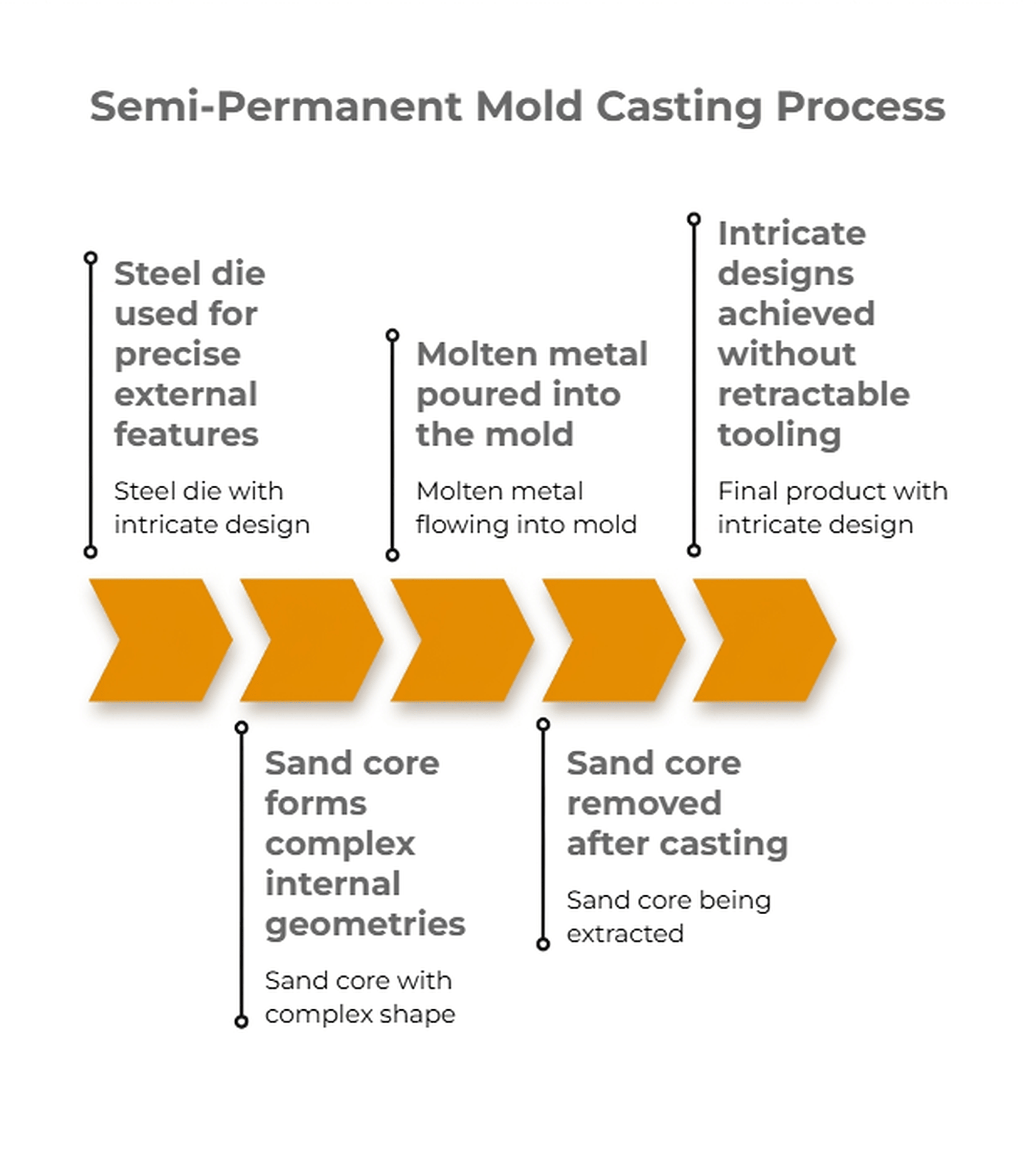
In practice, the semi-permanent mold casting process uses a steel die for precise external features and a sand core to form complex internal geometries, enabling cored bores and undercuts that are not possible with solid dies. After casting, the sand core is removed, allowing intricate designs without the need for retractable tooling.
This method delivers greater internal flexibility than permanent mold casting, with trade-offs in labor, cycle time, and core costs. While internal surfaces are rougher, and tolerances depend on core accuracy, it excels for parts needing complex internals.
How does it differ from other casting methods? The fundamental distinction lies in the combination of permanent and expendable elements: fully permanent mold casting is more efficient for simpler, externally defined shapes, but cannot produce intricate internal channels or negative-draft features.
Sand casting, on the other hand, allows for nearly limitless internal complexity but at the expense of surface finish, repeatability, and dimensional tolerance. The semi-permanent mold casting process delivers a unique value proposition by pairing the dimensional control and surface finish of a steel die with the design freedom of sand cores, making it the optimal choice for components that demand both.
Fully permanent mold casting is more efficient for simpler shapes. Expendable sand cores enable internal galleries and thin walls, with success dependent on core strength, alloy flow, and precise thermal management.
Casting cycle:
- Mold setup
- Core insertion
- Gravity or tilt pour
- Controlled solidification
- Ejection
- Core removal
Downstream operations:
- Inspection
- Heat treating
- Machining
- Assembly
The pouring method is matched to part requirements.
Procast’s integrated engineering, Solidification Analysis, Tool & Die, sand core production, CNC machining, and ISO 9001:2015 quality ensure every stage is managed in-house for complete accountability.
What is semi-permanent mold casting in sand casting used for? This hybrid process is used primarily when a part requires both the surface finish and dimensional accuracy of a permanent mold, and the intricate internal geometry achievable only with sand cores. Semi-permanent mold casting is selected for components with negative draft geometries that require pressure integrity and for complex internal features that cannot be formed in rigid dies.
It excels where sand casting’s variable tolerances and surface finish would compromise function or downstream processing. Common applications include fluid-handling parts, hydraulic manifolds, and housings with cored galleries, where both internal complexity and external quality are essential.
Application Matrix: Industry Deployment and Project Suitability
The semi-permanent mold casting process is best suited to medium-volume programs that demand pressure-tight or internally cored aluminum parts with tighter tolerances and finer finishes than sand casting can achieve, without the tooling capital required for high-pressure die casting. Suitability turns on three variables: annual volume, tolerance and integrity requirements, and total cost of ownership across tooling, machining, and scrap.
Selecting the right casting method for your project
Choosing a route is a constrained optimization, not a preference. Mapping the casting process steps against three axes clarifies the decision quickly:
Volume is the first: the economic sweet spot is medium volume. Below a few hundred parts, hard tooling rarely amortizes and sand or additive routes win; above the tens-of-thousands ceiling, high-pressure die casting’s cycle time begins to dominate landed cost. Between those bounds — commonly several hundred to tens of thousands of pieces per program — semi-permanent tooling tends to return the lowest cost per part, at roughly a tenth of the cost of comparable die-cast tooling.
Tolerance and integrity form the second axis. Die-formed surfaces hold tighter, more repeatable dimensions, and pressure-tight walls benefit from the chill-driven density of a steel cavity.
Total cost of ownership is the third: it is critical to weigh tooling, per-part cycle, shakeout and handling labor, machining stock, and expected scrap together rather than judging tooling price in isolation.
When engineers ask what considerations they should keep in mind when deciding whether semi-permanent mold casting is suitable for a specific project or material, the disciplined answer reduces to those three axes plus one material check: does the alloy tolerate a rigid, restraining cavity without hot-tearing?
Key industries and component examples
What considerations should I keep in mind when deciding whether semi-permanent mold casting is suitable for my specific project or material? The primary considerations are:
- Annual volume: Medium-volume production (typically 500 to 50,000 pieces) is the economic sweet spot. Lower volumes may not justify tooling investment, while higher volumes may favor high-pressure die casting.
- Geometry and complexity: If your part requires internal passages, undercuts, or negative draft features that cannot be formed with a rigid steel die alone, semi-permanent mold casting is likely the optimal route.
- Tolerance and surface finish: Expect die-formed faces to meet tighter dimensional tolerances and lower surface roughness than sand casting, while internal sand-cored features will have a coarser finish.
- Material behavior: The selected alloy must possess high fluidity, low solidification shrinkage, and good hot-tear resistance to perform reliably in a steel cavity. Silicon-rich aluminum alloys and certain zinc alloys are preferred.
- Total cost of ownership: Consider not only tooling and per-part cost, but also downstream machining, inspection, and scrap rates. Integrated engineering and simulation can mitigate risk and optimize outcomes.
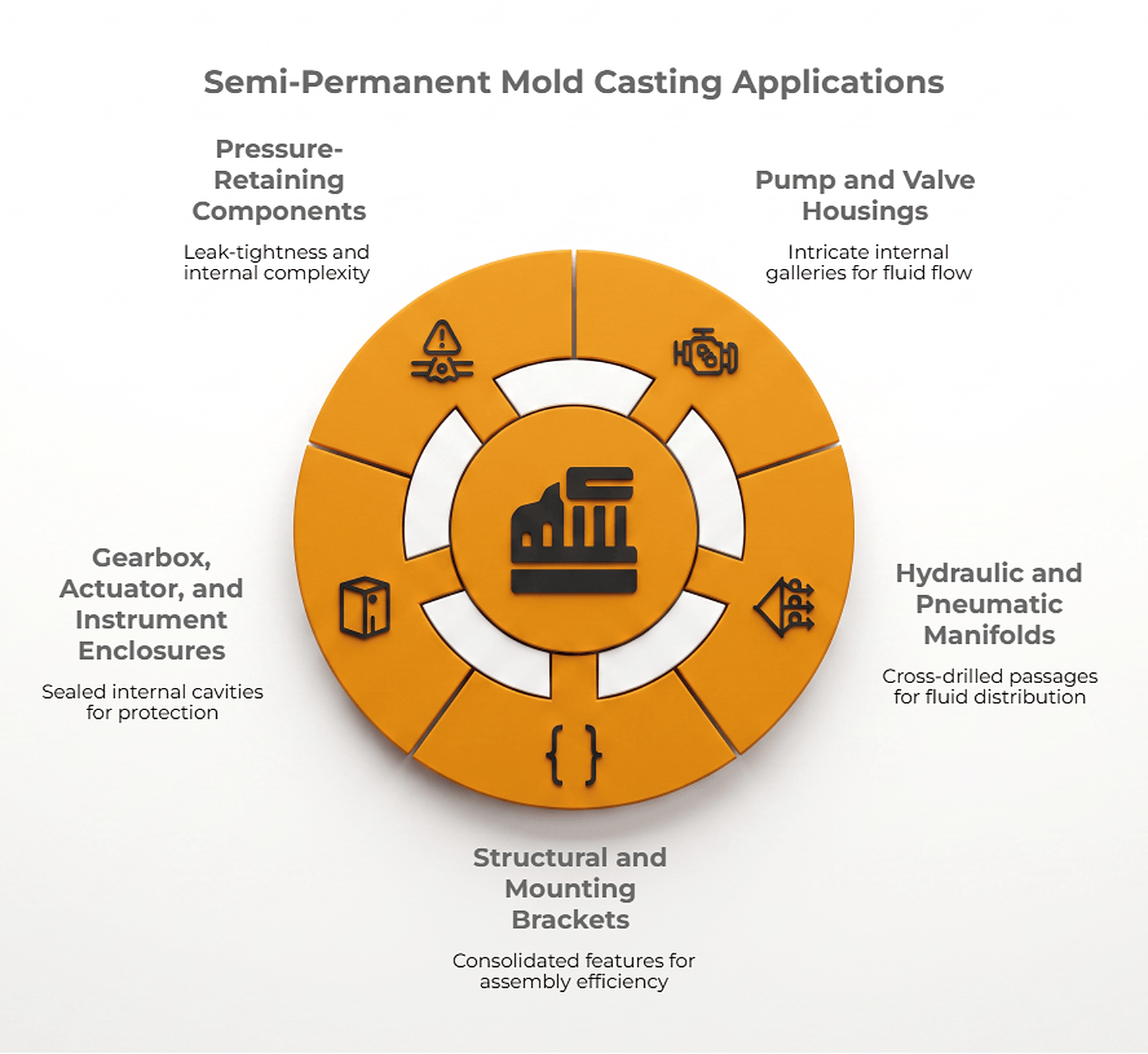
What are some examples of parts or products that are typically made using semi-permanent mold casting? The process excels at producing:
- Pump and valve housings, and valve blocks with intricate internal galleries
- Hydraulic and pneumatic manifolds with cross-drilled passages
- Structural and mounting brackets requiring consolidated features for assembly efficiency
- Gearbox, actuator, and instrument enclosures with sealed internal cavities
- Pressure-retaining components and fluid-distribution devices where leak-tightness and internal complexity are critical
What are the typical applications or industries that benefit most from using semi-permanent mold casting? The method is widely deployed in sectors where medium volumes and internal complexity are decisive:
- Industrial and commercial equipment manufacturing
- Fluid power and hydraulics (e.g., pumps, valves, manifolds)
- Transportation (including automotive, heavy vehicle, and rail components)
- Instrumentation and controls (precision enclosures, sensor housings)
- Energy and utility hardware requiring pressure integrity and custom internal geometries
These examples and industry applications are not exhaustive, but they reflect the essential strengths of semi-permanent mold casting: the ability to deliver custom aluminum castings with complex internal features at a cost and quality level that bridges the gap between sand and die casting. Because each program is engineered to print, the process is fundamentally a custom solution, rather than a catalog offering. This makes it especially valuable for organizations seeking a turnkey aluminum casting partner capable of supporting the entire lifecycle from engineering and tooling design and casting process simulation to finished, inspected assemblies.
Metallurgy and Surface Performance Benchmarks
The dominant alloys are A356, 413, and 319, chosen for silicon-driven fluidity and feedability, with select zinc alloys covering lower-temperature, high-precision work. Achievable as-cast surface roughness typically ranges from 160 to 400 RMS (appreciably finer than sand casting), governed by mold coating, thermal management, and gating.
Compatible alloys and material constraints
Alloy selection is bounded by three castability levers inside a reusable metal cavity: fluidity, solidification shrinkage, and hot-tear resistance. Because a steel die is rigid and chills quickly, it restrains a casting as it contracts; an alloy with poor hot-tear resistance will crack under that restraint. Silicon-bearing systems that stay fluid and freeze coherently therefore dominate the field:
- 3xx.x Al-Si-Mg (A356) and Al-Si-Cu-Mg (319): the structural and pressure-tight workhorse families; A356 balances strength, ductility, and castability, while 319 adds elevated-temperature strength.
- 4xx.x near-eutectic aluminum-silicon (B413): the highest fluidity, favored for thin sections and intricate fill where feed distance is long.
- Zinc alloys such as ZA-12: a lower pour temperature, providing excellent as-cast detail and dimensional stability for precision housings.
When specifiers ask what types of alloys can be used in the semi-permanent mold casting process and whether material limitations apply, the constraint is castability as much as chemistry. The broader permanent- and semi-permanent-mold family has been extended to higher-strength 2xx.x copper-bearing and 7xx.x zinc-magnesium aluminum alloys for structural service, but these are more prone to hot tearing, demanding grain refinement, controlled feeding, and often requiring solidification modeling to run reliably. Those higher-strength families describe the process’s reach, not a universal drop-in for every cavity.
The same reusable cavity is also what lets the process hold down the two dominant defect classes that erode pressure integrity: shrinkage porosity and gas porosity, the same two that challenge low pressure die casting. Shrinkage is managed by directional solidification, in which the steel die extracts heat rapidly and predictably. Therefore, with a deliberately staged thermal profile and correctly placed risers, the casting freezes progressively toward liquid feed metal, keeping the last-to-solidify region connected to a reservoir rather than isolating a starved pocket.
Research by the American Foundry Society has examined how core type, resin content, and knock-out time influence dimensional variation and shrinkage behavior in semi-permanent mold aluminum castings, underscoring how closely shrinkage outcomes are tied to core practice rather than to die design alone. Solidification Analysis makes that behavior visible before tooling is cut, positioning risers, gating, and chills to eliminate hot spots by design instead of by trial.
Gas porosity is attacked on two fronts: a low-turbulence runner and gating strategy, or a controlled tilt that fills the cavity without aspirating air or folding oxide films into the melt. Meanwhile, the sand cores are deliberately vented so that, as the binder heats, the gases evolved escape through the cores rather than being trapped at the metal–core interface. The net result is a denser, more pressure-tight casting than sand routes deliver. This explains why air decay and underwater pressure testing up to 150 psi are practical acceptance criteria for parts run this way.
Achieving superior surface profiles
The best aluminum casting surface finish achievable in this process comes from the die-formed faces, where a preheated, coated steel cavity reproduces a fine as-cast texture, typically on the order of 160 to 400 RMS. Sand-cored internal surfaces are inherently coarser, typical of bonded-sand contact.
Three foundry controls govern the outcome. Mold coating comes first: a base and insulating coat, plus a boron-nitride release layer, tune heat extraction and sharpen surface reproduction on low-draft faces. Thermal management follows: preheating the die to a steady-state operating temperature and staging cooling passages controls skin formation and local solidification rate. Gating closes the set: a runner and gating strategy that fills without turbulence prevents the oxide films and surface laps that degrade an otherwise clean face.
What types of alloys can be used in the semi-permanent mold casting process, and are there any material limitations? The process is optimized for aluminum alloys in the 3xx.x (A356, 319) and 4xx.x (B413) families, as well as zinc alloys such as ZA-12. These materials are selected for their high fluidity, low solidification shrinkage, and excellent hot-tear resistance, all of which are critical for achieving both superior surface finish and dimensional accuracy in a steel cavity.
Material limitations exist: alloys with poor hot-tear resistance or inadequate fluidity may not reliably fill thin sections or complex features. Furthermore, higher-strength alloys such as 2xx.x and 7xx.x may require advanced process controls, including grain refinement and precise thermal management, to avoid cracking or porosity.
In practice, Procast leverages in-house engineering and Solidification Analysis to validate alloy selection and process parameters prior to tooling, ensuring that the chosen material meets both the surface and structural requirements of the application. This approach minimizes risk and maximizes the likelihood of achieving the desired surface profile and mechanical properties, even in challenging geometries.
Mechanical Performance and Defect Mitigation
Comparing Quality, Strength, and Structural Integrity
Differences rooted in grain structure, density, and defect profile are most apparent when evaluating the quality or strength of castings produced by the semi-permanent mold casting process versus those produced by fully permanent or fully sand molds. The semi-permanent process yields a finer grain structure and higher density in die-formed regions than sand casting, due to rapid heat extraction and directional solidification imparted by the steel cavity. This results in improved mechanical properties, including increased tensile strength and pressure integrity, particularly in critical wall sections.
Compared to fully permanent mold casting, semi-permanent castings offer nearly equivalent external quality and dimensional control, but with the added benefit of complex internal geometries enabled by sand cores. The trade-off is that cored internal surfaces exhibit slightly coarser grain and lower density than die-formed faces, though both far exceed the porosity and grain coarseness typical of sand casting. In direct comparison, semi-permanent castings achieve a balanced profile: superior to sand casting in both strength and finish, and approaching the performance of permanent molds wherever the steel die governs solidification.
The main advantage of semi-permanent mold casting over traditional permanent mold casting is the ability to produce intricate internal passages, undercuts, and negative-draft features without the need for complex retractable cores or slides, and at a lower tooling cost. The disadvantages are the added steps and costs associated with core setting and shakeout, slightly rougher cored surfaces, and a marginally higher tolerance stack due to core-to-cavity registration.
Compared to sand casting, semi-permanent casting offers higher repeatability, improved mechanical properties, and better surface finish, but requires greater upfront tooling investment. These distinctions are especially relevant for medium-volume programs where both complexity and performance are required.
Engineering Solutions for Porosity and Defects
How does semi-permanent mold casting reduce porosity and defects? Porosity and other casting anomalies are a primary concern in both semi-permanent and low-pressure die casting. Semi-permanent castings deliver surface quality and density close to fully permanent molds, while offering greater flexibility for complex internal features. Engineered sand cores and steel dies produce castings that exceed sand casting in strength, pressure integrity, and dimensional consistency.
The semi-permanent mold casting process reduces defects by promoting directional solidification and precise core venting. Rapid heat extraction through the steel die channels promotes solidification toward risers, minimizing shrinkage porosity. Solidification Analysis is used during engineering to optimize thermal gradients and eliminate hot spots before tooling is built.
How do castings from this process compare to those made with fully permanent or fully sand molds? The semi-permanent process produces castings with superior mechanical properties and lower defect rates than sand casting, due to the rapid solidification and denser grain structure achieved in the steel die regions. While fully permanent mold castings may offer the highest density and surface finish overall, semi-permanent castings closely match these qualities externally and provide enhanced design flexibility for complex internal geometries. The combination of engineered sand cores and steel dies yields castings that outperform sand castings in both strength and pressure integrity while maintaining the dimensional accuracy and repeatability expected of permanent mold processes.
Gas porosity, a common concern in low-pressure die casting, is minimized through precise gating, low-turbulence filling, and tilt-pour techniques that limit oxide formation. Vented sand cores allow gases to escape, preventing entrapment at the metal–core interface. This combination of thermal control and gas management delivers castings with reduced defects, high pressure integrity, and consistent mechanical properties, meeting demanding standards such as air decay and underwater pressure testing up to 150 psi for critical industrial applications.
What are the main advantages and disadvantages of semi-permanent mold casting compared to traditional permanent mold casting? The primary advantage is the ability to create complex internal features, such as intricate channels, undercuts, and negative-draft geometries, by integrating sand cores into reusable steel dies. This flexibility eliminates the need for costly retractable cores or slides, reducing tooling costs to approximately one-tenth of traditional die casting for medium-volume runs. The process also delivers excellent repeatability, pressure integrity, and surface finish, enhanced by in-house engineering and simulation.
Disadvantages include additional process steps for core setting and shakeout, slightly rougher internal surfaces, and a marginally higher tolerance stack due to core-to-cavity registration. However, these are offset by the process’s ability to meet demanding performance and geometric requirements at a cost-effective tooling investment, making it ideal for medium-volume industrial programs.
Geometric Limits: Intricate Channels and Thin-Wall Engineering
Can complex internal geometries or thin walls be produced with semi-permanent mold casting? Absolutely. This is a core strength of the semi-permanent mold casting process. The defining advantage lies in the ability to produce highly complex internal geometries and thin-walled sections that are not achievable with fully permanent or fully sand molds alone.
Expendable sand cores unlock the design freedom to incorporate undercuts, blind passages, and negative-draft features, enabling custom aluminum casting solutions for parts such as pump housings, manifolds, and instrument enclosures. These cores can be precisely engineered and positioned within the steel die, allowing for the consolidation of multiple internal features into a single, pressure-tight casting.
Practical wall-thickness limits are governed by alloy fluidity, die preheat, and core strength. For thin-wall applications, high-fluidity alloys such as B413 (4xx.x) are preferred. The process is further enhanced by the use of tilt-pour aluminum casting techniques. Tilt-pour fills the cavity smoothly, minimizing turbulence and reducing the risk of cold shuts or oxide film entrapment, critical for achieving uniform fill in thin, intricate sections. This process capability is not a superlative claim about any supplier, but a proven method for optimizing thin-section quality and repeatability in semi-permanent mold casting.
Core venting becomes critical as wall thickness decreases; precise core design with controlled permeability ensures defect-free filling and solidification, even in complex shapes. For aluminum alloys, practical walls start at 3/16 in, with thinner sections possible using advanced simulation and process controls.
Semi-permanent mold casting delivers pressure-tight aluminum and zinc parts with complex internals and thin walls. By combining reusable steel dies, sand cores, in-house engineering, and rigorous quality controls, this process enables cost-effective, medium-volume production with excellent dimensional accuracy — ideal for fluid-power manifolds, instrument housings, and intricate brackets.
Final Insights
Semi-permanent mold casting offers industrial clients a precise, cost-effective solution for medium-volume aluminum and zinc components with complex geometries and demanding performance criteria. Procast’s integrated approach, combining reusable steel dies, engineered sand cores, in-house Solidification Analysis, and ISO 9001:2015 certified quality controls, delivers turnkey castings with reliable pressure integrity, tight tolerances, and superior surface finish.
For projects requiring intricate internals or pressure-tight results with tooling optimized for medium runs, connect with Procast’s engineering team to leverage our expertise in permanent mold process simulation, custom tooling, and advanced quality assurance. Contact us today to discuss how our semi-permanent mold casting solutions can advance your next industrial program.